Hydronic Balancing: How It Works
Hydronic balancing means adjusting a heating and cooling system so that each convector receives exactly the water flow rate it needs. Not too much, not too little.
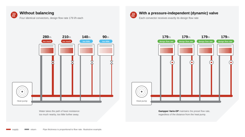
Without balancing, water takes the path of least resistance. Convectors close to the manifold or heat pump often receive too much flow, while those further away from the pump receive too little. The result is familiar in practice: one room heats up quickly, while another takes longer or fails to warm up at all. The customer calls with a comfort complaint.
Balancing gives each convector its own precalculated flow rate. This rate is determined by the unit’s output and the supply and return water temperatures it was designed for. This ensures that water is distributed throughout the system as intended in the design.
Why It Matters More with a Heat Pump
With a boiler running at 70 °C, poor system balancing is less noticeable. At such high temperatures, the heat emitters are often oversized. A low water flow rate also tends to have only a limited impact on their output at high temperatures. A heat pump works differently.
- Small ΔT, high flow rates. A heat pump operates with a small temperature difference between supply and return: often 5 K in new builds and 10 K in renovations with existing pipework. A boiler traditionally operates with 20 K. The smaller the ΔT, the more water must flow through the system to deliver the same output. This magnifies imbalances in flow distribution.
- Little temperature headroom. In a low-temperature heating system, the heat pump runs at a supply temperature of around 35 °C for most of the heating season. If a unit delivers insufficient output because its water flow rate is too low, there is little scope to compensate by raising the water temperature.
- A higher heating curve reduces efficiency. If the furthest convector receives too little water, that room will not warm up. The instinctive response is to raise the heating curve (water temperature). But every degree of increase in supply temperature reduces the heat pump’s efficiency.
- Return temperature too high. Convectors with excessive flow allow water to pass through before it has cooled sufficiently. The return temperature rises above its design value, and the heat pump becomes more prone to short cycling: frequent switching on and off, resulting in greater wear and lower efficiency.
In short, hydronic balancing is an essential part of a heat pump installation, ensuring it delivers the efficiency the customer has paid for.
Heating and Cooling Require Carefully Matched Temperature Regimes
When a heat pump is also used for cooling, there are two design temperature regimes to consider: one for heating and one for cooling. The unit size and temperature regimes are often selected so that the water flow rates for heating and cooling are similar. This allows the flow rate at the unit’s valve to be set once for both functions.
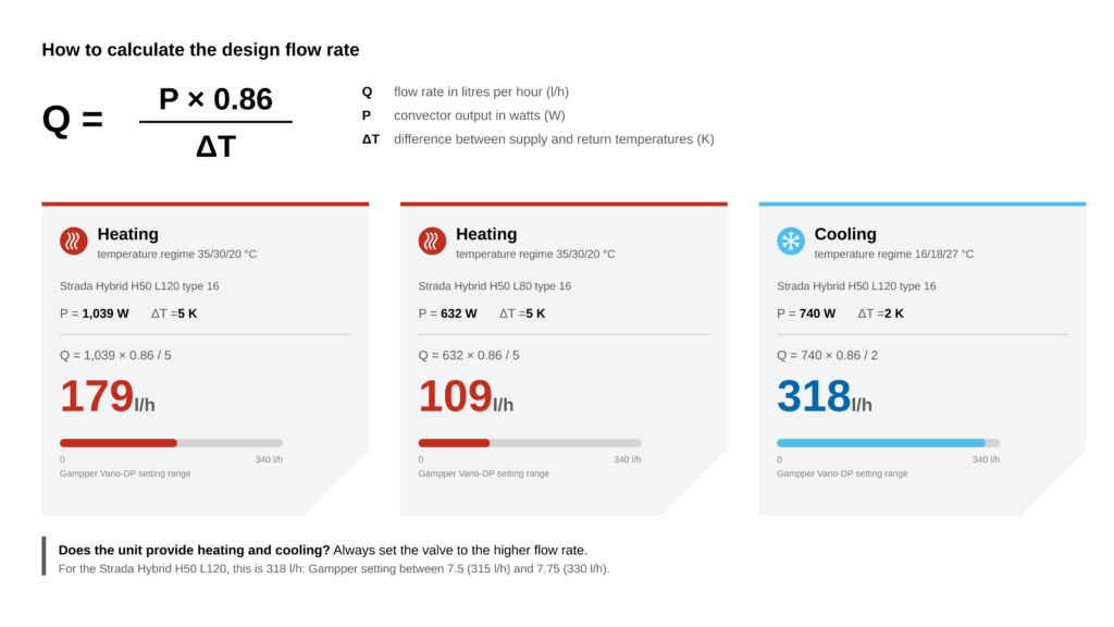
The design flow rate for each unit is calculated using Q = P × 0.86 / ΔT (Q in l/h, P in W, ΔT in K).
Take a Strada Hybrid H50 L120 type 16 as an example:
| Temperature regime | Output | ΔT | Design flow rate |
|---|---|---|---|
| Heating 35/30 °C, room temperature 20 °C | 1,039 W | 5 K | 180 l/h |
| Cooling 16/19 °C, room temperature 27 °C | 701 W | 3 K | 200 l/h |
Which flow rate should you set for a unit that provides both heating and cooling? Always the higher of the two. For the Strada Hybrid in this example, that is the cooling flow rate of 200 l/h.
Static or Dynamic Balancing?
There are two ways to achieve the calculated flow rate in practice.
Static balancing uses a presettable radiator valve or lockshield valve. You set a fixed resistance for each unit, matched to the design conditions. This works, but only as long as the differential pressure across the unit and its valve remains constant. If thermostatic valves in other rooms close and the circulation pump does not adjust its head, the differential pressure rises and the open units receive excessive flow. If another convector is added later, the entire system needs to be rebalanced.
Dynamic balancing uses a pressure-independent (dynamic) valve. This combines a balancing valve and a differential pressure regulator in a single valve. You set the required flow rate, and the valve maintains it even when the differential pressure in the system changes.
| Static | Dynamic | |
|---|---|---|
| Setting | Calculate and measure the flow rate for each unit | Set the flow rate directly using an adjustment key |
| At partial load | Open units receive excessive flow | Flow rate remains constant |
| Adding a unit | Rebalance the system | Set only the new valve |
| Heating and cooling | One fixed resistance for two temperature regimes | Set to the higher design flow rate |
| Requirement | Accurate balancing calculations | A pump with sufficient head |
For a simple boiler system with radiators, static balancing may be perfectly adequate. For a heat pump system with convectors, high flow rates and often cooling as well, dynamic balancing offers greater benefits: it saves time during commissioning and maintains balanced flow distribution at partial load. Pay attention to the pump, however: it must provide sufficient head for every valve.
The Gampper Vario-DP Valve
For heat pump systems with Jaga convectors, we use the Vario-DP valve from Gampper. Vario-DP is the name of the technology: a pressure-independent (dynamic) valve that combines control and balancing.
How it works: the valve contains a patented Vario-DP insert. When the differential pressure in the system rises, the insert automatically closes slightly. When the differential pressure drops, it opens further. This keeps the flow rate set with the adjustment key constant.
| Specification | Value |
|---|---|
| Flow adjustment range | 20–340 l/h, continuously adjustable using a key |
| Nominal pressure | PN 10 |
| Maximum water temperature | 120 °C |
| Thread | M30 × 1.5 |
| Seal | Valve stem with a double O-ring, maintenance-free |
With a range of up to 340 l/h, the valve also accommodates the high flow rates required by convectors in cooling mode. The previous valve (Heimeier Eclipse) had a maximum flow rate of 150 l/h; the Strada Hybrid in the example requires 200 l/h for cooling.
Setting the flow rate in three steps
- Calculate the design flow rate or look it up in the selection tool. If the unit provides both heating and cooling, calculate the flow rate for both temperature regimes and use the higher value.
- Find the corresponding setting in Gampper’s adjustment table, from setting 1 (20 l/h) to setting 8 (340 l/h).
- Turn the insert to that setting using the adjustment key. That’s it—no flow measurements or further adjustments are needed for each unit.
Switching to cooling: a thermostatic head closes as the room warms up. This is exactly what you want during heating, but during cooling it blocks the chilled water flow. For Jaga Hybrid units, use either the HC head, which you fully open for the cooling season, or the H/C adapter, which locks the valve in the open position for cooling.
Which Connection Sets Include a Gampper Valve?
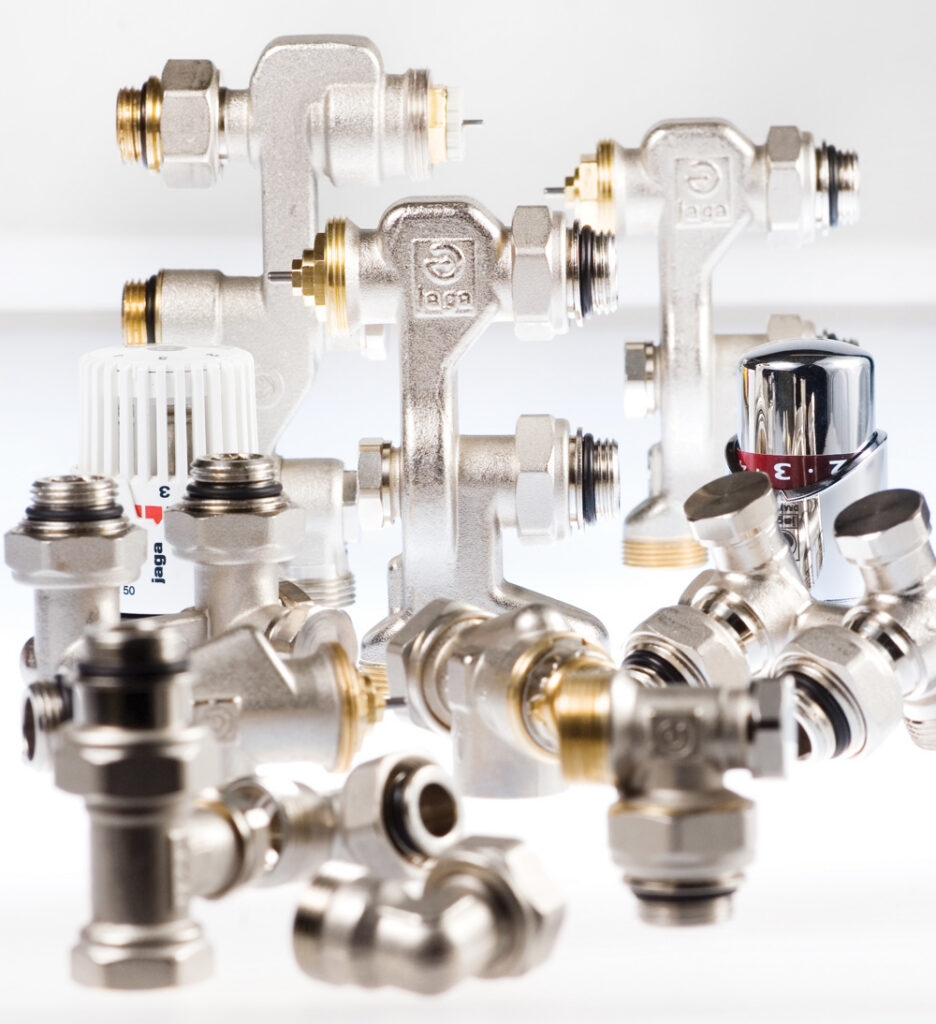
A connection set with Gampper’s Vario-DP valve is available for almost every Jaga convector: for wall or floor connections, with a thermostatic head or a thermal actuator. Look for the description “pressure-independent flow control (20–340 l/h)”: these sets provide dynamic balancing. If a Kv value is listed, the set uses static balancing, and the flow rate still depends on the differential pressure across the valve.
To find the right set for your unit and connection type, use the selection guide on our Connection Sets & Valves page. If you also want cooling, order the code 5 version with an H/C adapter, or choose the HC head.
Conclusion
With a heat pump, hydronic balancing is an essential part of delivering a system that performs as promised in the customer’s home. The steps in this article give you everything you need:
- Calculate the design flow rate for each unit using Q = P × 0.86 / ΔT, based on the ΔT of the actual system design.
- Does the unit also provide cooling? Calculate both temperature regimes and use the higher flow rate, usually the cooling flow rate.
- Choose a connection set with Gampper’s Vario-DP valve to maintain the set flow rate without having to measure it at each unit.
- Use the adjustment key to set the valve to the position specified in Gampper’s adjustment table.
- Before the cooling season, fully open the HC head or fit the H/C adapter.
This allows you to lower the supply temperature, prevents short cycling and cold rooms, and ensures compliance with the hydronic balancing requirement.
Frequently Asked Questions About Hydronic Balancing
What Are the Benefits of Hydronic Balancing?
That depends on how unevenly the flow was distributed throughout the system. With a heat pump, the main benefits come from avoiding a higher heating curve and preventing short cycling. Cold rooms and comfort complaints are also resolved, and the pump runs no harder than necessary.
What Is the Difference Between Static and Dynamic Balancing?
Static balancing sets a fixed resistance for each unit and works well as long as the pressure remains constant. Dynamic balancing uses a pressure-independent (dynamic) valve to maintain the set flow rate, even when valves elsewhere in the system close.
What Flow Rate Should I Set the Valve to If the Unit Provides Both Heating and Cooling?
Always use the higher design flow rate. For convectors, this is usually the cooling flow rate.
Do I Need to Make Any Adjustments When Switching from Heating to Cooling?
Yes. A thermostatic head closes when the room is warm, blocking the chilled water flow. For Jaga Hybrid units, fully open the HC head or use the H/C adapter.